
Overview
When servicing a Just Add Power installation—whether recently deployed or legacy—critical system details are not always available. It’s common to arrive on-site expecting a quick task, only to discover that missing documentation or unfamiliarity with the system significantly extends the visit.
This article is designed to help you:
- Identify issues as quickly and efficiently as possible
- Identify the Just Add Power system type
- Take inventory of and document the system
How to use this article: Start with Quick System Identification to narrow the system type fast. If a Report File is available, review it next. Use Gather System Details only if you still need to confirm hardware, switch access, or device inventory. As you work, capture information in the Takeover Form so findings are documented and usable beyond the site visit.
Goal: Get to a confident system type and a documented inventory with minimal guesswork.
Quick System Identification
Use the checks below to quickly narrow down the system type. If more than one result matches, continue to Gather System Details to confirm.
- Report File available? → Use it first (fastest path).
- Device subnet is 172.27.x.x? → AMP Standardized (VLAN)
- Device subnet is 172.17.x.x? → AMP Alternate (Multicast)
- Encoders start on port 2 and run sequentially? → JADConfig
- Decoders start on port 1 and run sequentially? → AMP Standardized (VLAN)
- No clear port pattern? → Custom or AMP Alternate (Multicast)
Tip: Take photos of switch port layouts and debug screens to capture details quickly, then use those photos to complete the Takeover Form accurately.
Fillable Form
Download the form below, complete it on-site, and send it to us if you would like assistance taking inventory of the jobsite.
For best results: Fill this out while on-site and include photos of switch labels, port layouts, and any Decoder debug screens.
Important: Photos help capture details quickly, but the Takeover Form is the official record of the system. Information should be transferred from photos into the form before leaving the site.
System Types
There are five system types that Just Add Power has supported over the years:
| System Type | Configuration Software | Control Type | Just Add Power Series | Installation Years | Support Status |
|---|---|---|---|---|---|
| AMP – VLAN | AMP Standardized | IP | Omega Series Ultra Series MaxColor Series |
2022–Present | Ongoing |
| AMP – Multicast | AMP Alternate | IP | Omega Series Ultra Series MaxColor Series |
2021–Present | Ongoing |
| JADConfig – VLAN | JADConfig | IP | 2G Series Omega Series Ultra Series |
2013–2022 | Ongoing |
| Custom Multicast | None Custom |
IP | 2G Series Omega Series Ultra Series MaxColor Series |
2016–2021 |
Limited Recommended by Support: convert to AMP Alternate (Multicast) (2G Series is not compatible with AMP) |
| Custom Serial Control | None Custom |
Serial Connected directly to switch |
1G Series 2G Series |
2009–2013 |
Limited Recommended by Support: convert to JADConfig (1G Series and 2G Series are not compatible with AMP) |
Support note: “Preferred” conversion paths are recommendations to bring older/custom systems onto a configuration method that is easier to support and document. They are not required to troubleshoot the current system.
Report File
If a Report File is available, review it first. It often eliminates the need to manually identify switch access, port assignments, and IP addressing.
Systems set up with JADConfig or AMP generate a Report File that provides:
- Number of Encoders
- Number of Decoders
- IP address, subnet mask, and default gateway for all Just Add Power devices
- Port location for all Just Add Power devices (VLAN systems)
- Switch model, IP address, username, and password (VLAN systems)
With the information in the Report File, an installer can inventory every device in the system and verify whether it is properly connected.
Next step: Use the Report File to confirm device counts and connectivity, then jump to Gather Details: Just Add Power Firmware if you suspect mismatched versions.
Tools to Bring to the Site With You
Just Add Power provides many software tools to troubleshoot a system, but some essentials are hardware items you should bring to every jobsite.
Minimum kit: Windows PC, PuTTY, a discovery scanner, and the correct console/USB-serial cables.
Optional but helpful: Spare power supply, headphones, and a known-good HDMI cable for quick isolation tests.
- Windows PC
- JADConfig software
- AMP software
- Bonjour Browser
- Docklight scripting
- PuTTY
- USB-to-serial adapter
- Console cable
- Headphones with 3.5mm (1/8") connector
- Power supply for Just Add Power devices
Gather System Details
Checklist: Work through the steps below in order. Stop once you can confidently identify the system type and document the information needed for service or Support.
- Capture: hardware series + switch model
- Confirm: switch IP + login method
- Document: Encoder/Decoder counts + port ranges
- Verify: device subnet + firmware version
- Record: control system (driver/platform)
Note: If a Report File is available, you may not need to complete every step below.
Tip: Take photos of labels, switch ports, and debug screens as you go.
These details help determine which system type you are working on:
- Just Add Power Hardware
- Switch Model
- Switch IP Address and Login
- Encoder Ports and Count
- Decoder Ports and Count
- Just Add Power IP Scheme
- Just Add Power Firmware Version
- Control System
Documentation reminder: The goal of gathering these details is a complete, readable system record. Transfer confirmed information into the Takeover Form so it can be referenced by Support or future technicians.
Gather Details: Just Add Power Hardware
Identify the Just Add Power hardware series used in the system. In most installations, all devices are the same series. Mixed-series systems exist, but they follow additional rules and are outside the scope of this article.
Goal: Identify the hardware series so you can determine likely configuration options and compatibility.
Record: Series name (MaxColor / Ultra / Omega / 2G / 1G), model numbers, and whether devices appear mixed-series.
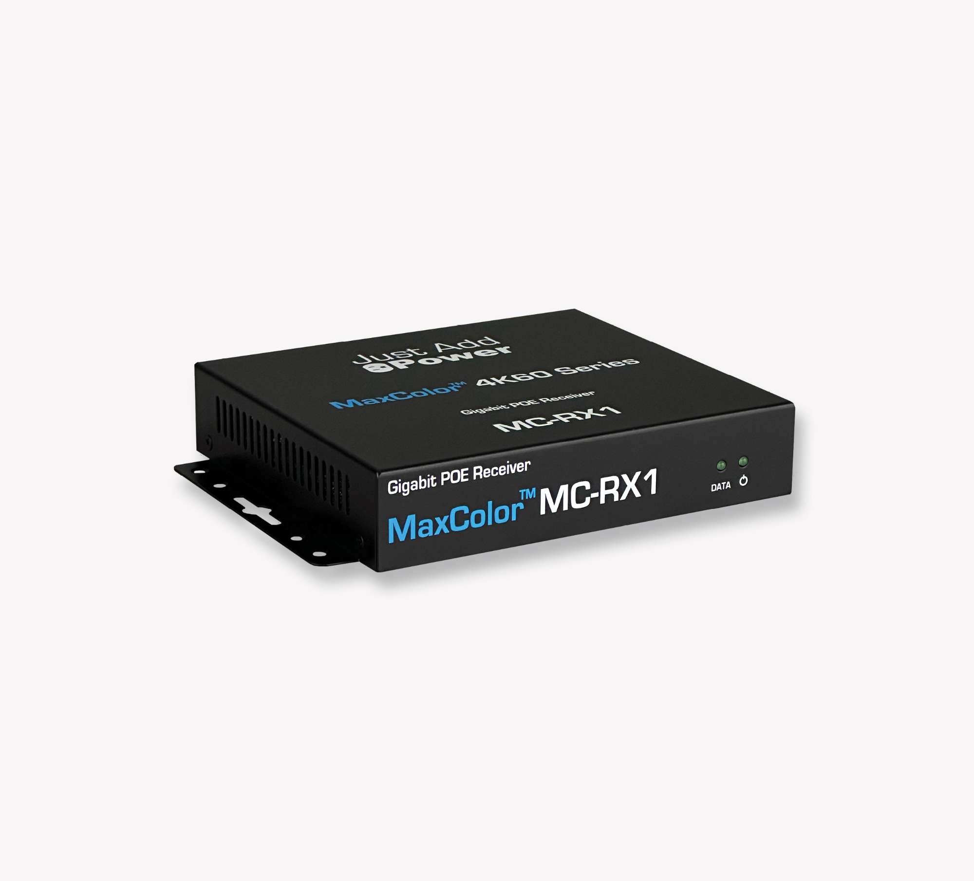
MAXCOLOR™ Series – Released in 2022 and supports 4K60, 36-bit color, 4:4:4
Ultra Series – Released in 2015 and supports 4K30, 30-bit color, 4:4:4
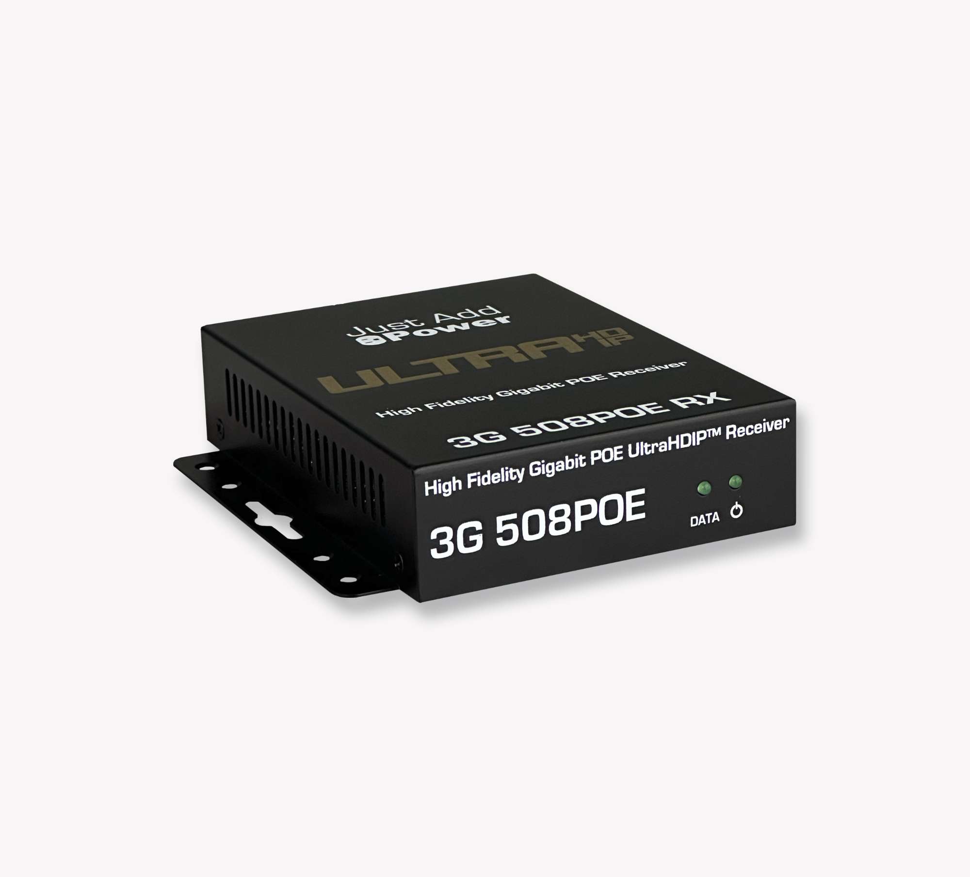
Omega Series – Released in 2016 as an upgrade to the 2G Series. Compatible with both 2G Series and Ultra Series.
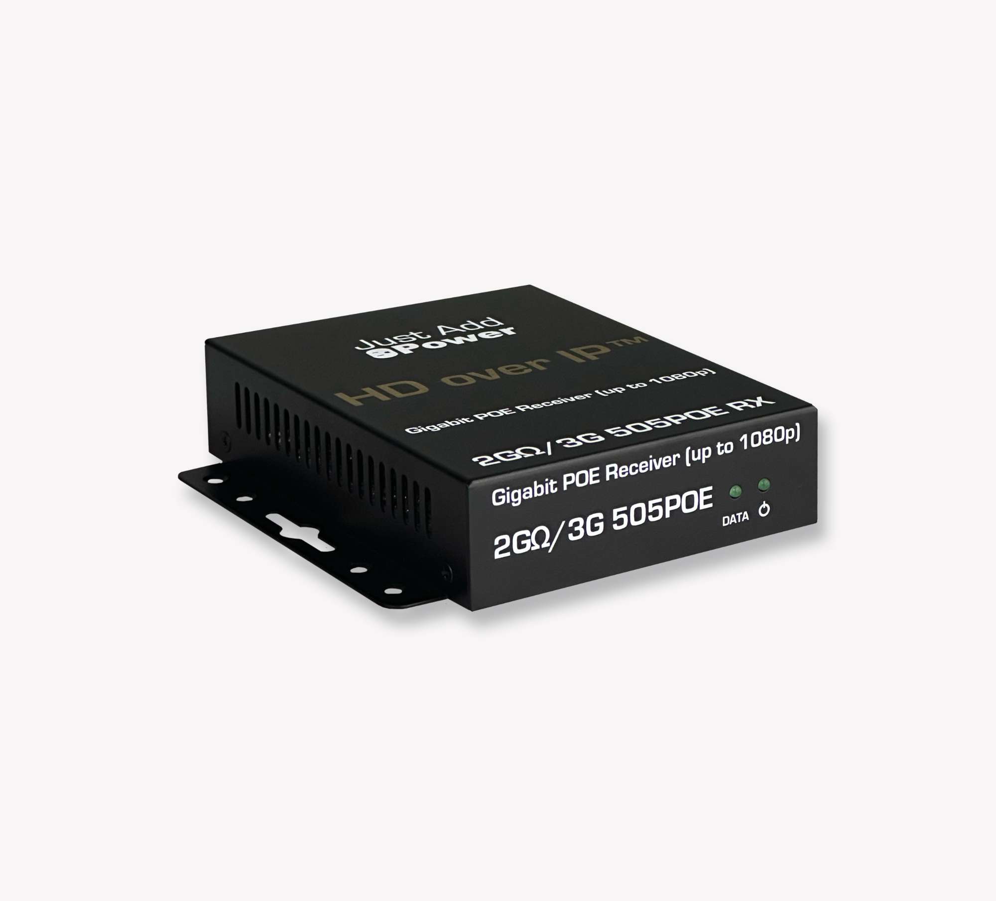
2G Series – Released in 2011 and supports 1080p. Compatible with Omega Series.

1G Series – Released in 2009 and supports 1080p on a 100 Mbps network.

Gather Details: Switch Model
Quick takeaway: If the switch is not on the JADConfig list, it is not a JADConfig system. If it is not on the AMP Standardized (VLAN) list, it is not an AMP Standardized (VLAN) system.
Goal: Determine whether JADConfig or AMP Standardized (VLAN) can be ruled out based on switch support lists.
Record: Manufacturer + exact model + quantity of switches (stacked / multiple).
List of switches supported by JADConfig. If the switch is not on this list, it is not a JADConfig system.
List of switches supported by AMP Standardized (VLAN). If the switch is not on this list, it is not an AMP Standardized (VLAN) system.
If the switch is not on either list, the system is likely AMP Alternate (Multicast) or one of the custom types.
To find the switch model:
- Locate the manufacturer sticker on the switch (or switches).
- Use the sticker to identify the switch model.
- If the sticker is missing, the model is often printed on the enclosure.
- If you can’t locate the model, call Tech Support with a serial connection from the switch to a PC.
- After identifying the switch model, continue to the next section.

Gather Details: Switch IP Address and Login
Logging into the switch (with a valid username and password) is often the first major hurdle when taking over a system. If you don’t know the switch IP address, you can usually find it using one of the methods below.
Goal: Identify the switch IP address and confirm you can log in (web UI/Telnet/console).
Record: Switch IP, access method, username/password (if provided), and whether access is confirmed.
Method 1: IPv4 Discovery Software
- Advanced IP Scanner: https://www.advanced-ip-scanner.com/
- Angry IP Scanner: https://angryip.org/
Discovery tools can scan an IPv4 subnet and list devices on the LAN. For each discovered device, you can typically see:
- IP Address
- Manufacturer
- MAC Address

Instructions:
- Identify the switch MAC address from the manufacturer sticker.
- Run Advanced IP Scanner or Angry IP Scanner.

- Match the switch MAC address to the device list in the scanner.
- The matching entry will show the switch IP address.
Method 2: Router Client List
Another option is to use the jobsite router to view connected clients. Router interfaces vary—if your router doesn’t provide this view (or discovery scanning fails), contact Support for assistance.

Gather Details: Encoder Ports and Count
Count the number of active Encoders and document their switch port connections. Encoder layouts often follow a pattern. Ignore unused/blank ports for now—those may be reserved for future expansion or reassignment.
Goal: Count active Encoders and document where they land on the switch to help identify system type and verify wiring.
Record: Total active Encoders + their port range(s) + any gaps + any non-J+P devices in the same range.
| Encoder Ports | System Type |
|---|---|
| Start on port 2 Sequential until the last Encoder |
JADConfig |
| Start after the last Decoder port Sequential until the last Encoder |
AMP Standardized (VLAN) |
| Any other layout No pattern |
Custom or AMP Alternate (Multicast) |
Tip: If ports are not sequential, take a photo of the switch LEDs and port labels—this is often faster than writing each one down.
Gather Details: Decoder Ports and Count
Count the number of active Decoders and document their switch port connections. Decoder layouts often follow a pattern. Ignore unused/blank ports for now—those may be reserved for future expansion or reassignment.
Goal: Count active Decoders and document where they land on the switch to validate expected port patterns.
Record: Total active Decoders + their port range(s) + any gaps + whether they begin on port 1 (common for AMP Standardized (VLAN)).
| Decoder Ports | System Type |
|---|---|
| Start after the last Encoder port Sequential until the last Decoder |
JADConfig |
| Start on port 1 Sequential until the last Decoder |
AMP Standardized (VLAN) |
| Any other layout No pattern |
Custom or AMP Alternate (Multicast) |
Gather Details: Just Add Power IPs
All Just Add Power devices will be in the same subnet. In some cases, the subnet can also help identify the system type.
Goal: Identify the subnet used by Just Add Power devices and compare it against known patterns.
Record: One device IP + subnet mask + gateway (if visible) + whether the subnet matches AMP/JADConfig patterns.
To find a device IP quickly, view a Decoder debug screen. One simple method is to disconnect video from an Encoder so the Decoder has no video to display.

| IP Address | System Type |
|---|---|
| 10.x.x.x 172.16.x.x 192.168.100.x 192.168.200.x |
JADConfig |
| 172.27.x.x | AMP Standardized (VLAN) |
| 172.17.x.x | AMP Alternate (Multicast) |
| Any other IP | No definite system type |
Gather Details: Just Add Power Firmware
All Just Add Power devices in a system must be on the same firmware version. You can view the firmware version on a Decoder debug screen.
Goal: Confirm all devices match firmware versions (mismatches can cause unstable behavior and discovery issues).
Record: Firmware version shown on the debug screen and whether all endpoints match.
If firmware versions do not match: Stop and contact Support before updating—mixed firmware can complicate troubleshooting.
Gather Details: Control System
Just Add Power provides drivers for many control systems. If the site is using an official Just Add Power driver, you can confirm compatibility on the Control page.
Goal: Identify what is controlling switching (driver/platform) so you can confirm compatibility and expected behavior.
Record: Control system brand/model + driver type (Just Add Power vs third-party/custom) + where it connects (network/serial).

