Overview
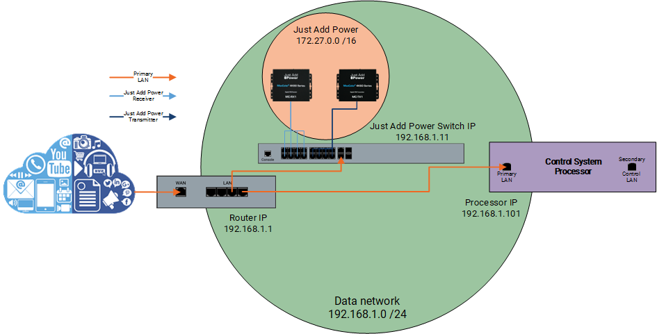
Some control system processors provide a secondary Control LAN port meant for internal devices that do not require Internet access. Just Add Power can be installed on this secondary Control LAN. However, this secondary Control LAN port does not allow communication outside of the subnet of the Control LAN; any communication meant for another subnet is routed through the primary LAN port instead. This routing behavior means that the typical static route options will not work and other adjustments are needed, as routing is a necessary part of a Just Add Power system.
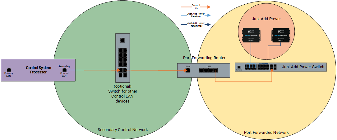
This article describes the process to configure a standalone router so that a control system processor's secondary Control LAN port can communicate with Just Add Power devices - which are on a different subnet - as if they are a part of the same subnet.
Extra Hardware Needed
Only one piece of extra hardware is needed: a router. It does not need to be a particularly robust router, but it must have these features:
- WAN port with a configurable Static IP and subnet mask
- LAN port with a configurable Static IP and subnet mask
- Port Forwarding for one port for matrix switching control. For endpoint and feature control, one forwarded port per Just Add Power device being controlled.
- Static Routing
Network Information
First, a few important network settings need to be determined, as many settings between the control system processor, port forwarding router, Just Add Power switch and devices, and the settings in the drivers must match. The two tables below hold the information that is needed for the setup to work. We have filled information in the table that fit the setup example, so please change necessary details to fit your installation.
Table 1 - IP Details
Rules for IP Details:
- All devices in the Control LAN Network must be in the same subnet
- All devices in the Port Forwarded Network must be in the same subnet
- The Control LAN Network and the Port Forwarded Network must be different subnets that do not overlap
- The Control LAN Network and the Primary LAN Network (the two network ports on the control system processor) must be different subnets that do not overlap
- The Primary LAN Network and the Port Forwarded Network do not interact, and will not produce any IP conflicts if they accidently overlap
- The Port Forwarded Network and the Just Add Power Network must be different subnets that do not overlap. Just Add Power uses 172.27.0.0 /16 by default, so just DON'T USE THAT SUBNET
| Device Name | Control LAN Network or Port Forwarded Network |
IP | Subnet Mask | Default Gateway |
|---|---|---|---|---|
| Control System Processor | Control LAN Network | 192.168.1.101 | 255.255.255.0 | (None) |
| Router WAN port | Control LAN Network | 192.168.1.11 | 255.255.255.0 | (None) |
| Router LAN port | Port Forwarded Network | 192.168.0.1 | 255.255.255.0 | (None) |
| Just Add Power Switch | Port Forwarded Network | 192.168.0.11 | 255.255.255.0 | 192.168.0.1 |
Table 2 - Port Forwarding List
Rules for Port Forwarding List:
- External forwarded port (WAN port) for the Matrix Control Receiver MUST be 23. Matrix Control only needs port forwarding for one device. We recommend Receiver 1.
- Internal forwarded port (LAN port) is ALWAYS 23
- External forwarded port (WAN port) for other Just Add Power devices should be a 4-digit or 5-digit number. Endpoint or feature control - IR, RS232, CEC, video wall, tiling layout, etc - needs port forwarding for each device being controlled.
| Just Add Power Device | WAN Port | LAN IP | LAN Port |
|---|---|---|---|
| Receiver 1 | 23 | 172.27.1.1 | 23 |
| Receiver 2 | 27102 | 172.27.1.2 | 23 |
| Receiver 3 | 27103 | 172.27.1.3 | 23 |
| Receiver 4 | 27104 | 172.27.1.4 | 23 |
| Receiver 5 | 27105 | 172.27.1.5 | 23 |
| Receiver 6 | 27106 | 172.27.1.6 | 23 |
| Receiver 7 | 27107 | 172.27.1.7 | 23 |
| Receiver 8 | 27108 | 172.27.1.8 | 23 |
| Receiver 9 | 27109 | 172.27.1.9 | 23 |
| Receiver 10 | 27110 | 172.27.1.10 | 23 |
| Transmitter 1 | 28101 | 172.27.101.254 | 23 |
| Transmitter 2 | 28102 | 172.27.102.254 | 23 |
| Transmitter 3 | 28103 | 172.27.103.254 | 23 |
| Transmitter 4 | 28104 | 172.27.104.254 | 23 |
| Transmitter 5 | 28105 | 172.27.105.254 | 23 |
Setup
We will be using the details in the tables above for this setup example. By the end, the configuration will look like this
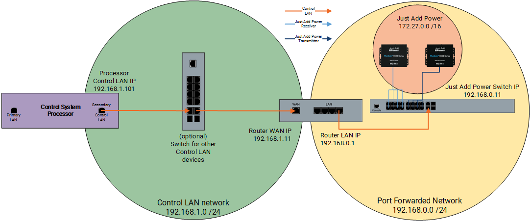
- Configure the control system processor secondary control LAN network adapter. We will use 192.168.1.101 /24 for this example.
- Connect your PC to a LAN port of the Port Forwarding Router. Login to the webUI.
- Configure the Internet/WAN port to be in the same network as the secondary control LAN. We will use 192.168.1.11 for this example. If this was a normal router, this is the port that is connected to the ISP's modem.
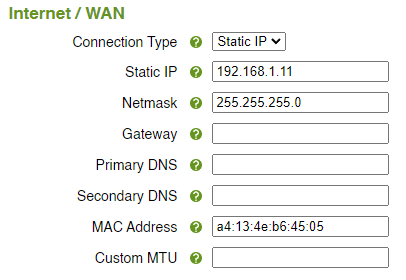
- Configure the Local Network/LAN port as its own network and assign the router an IP. We will use 192.168.0.1 for this example. If this was a normal router, this is the Default Gateway value for all devices in the network.

- Connect a LAN port of the Port Forwarding Router to the last port of the Just Add Power switch. Run AMP to configure the switch and all Just Add Power devices. The Just Add Power switch is part of the Port Forwarded Network (NOT part of the control LAN network):
- Switch IP Address: 192.168.0.11
- Switch Netmask: 255.255.255.0
- Switch Gateway: 192.168.0.1
- Just Add Power devices: 172.27.0.0 /16 (default)
- After AMP is done, open the Report File with IP addresses for all Just Add Power devices
- Login to the webUI of the Port Forwarding Router (192.168.0.1)
- Add a Static Route for the Just Add Power devices. This is the same thing you would do if this was the normal Internet router in a Just Add Power system.

- Go to the Port Forwarding section of the router

- Add a forwarded port for each Just Add Power device that needs to be controlled. For Matrix Control, only one device is needed. For Endpoint or Feature Control, one entry per device is needed.
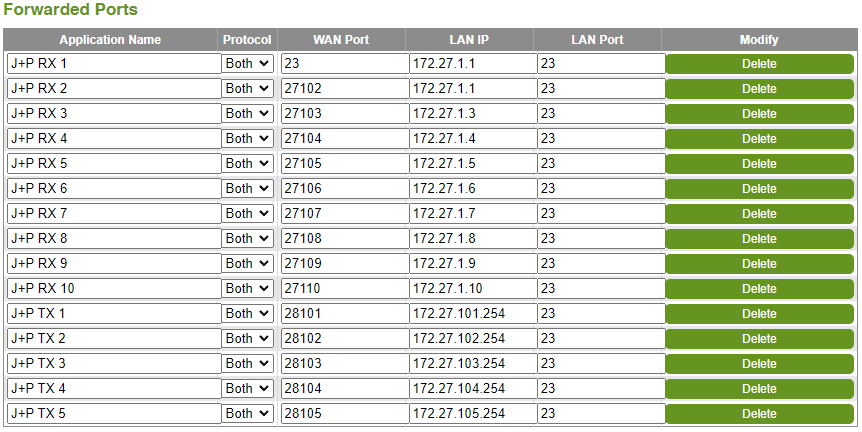
- For Matrix Control, go to the control system programming interface, select the Just Add Power switching driver, and enter the router WAN IP for the
CONTROL_UNIT_IP_ADDRESS- Router WAN IP: 192.168.1.11
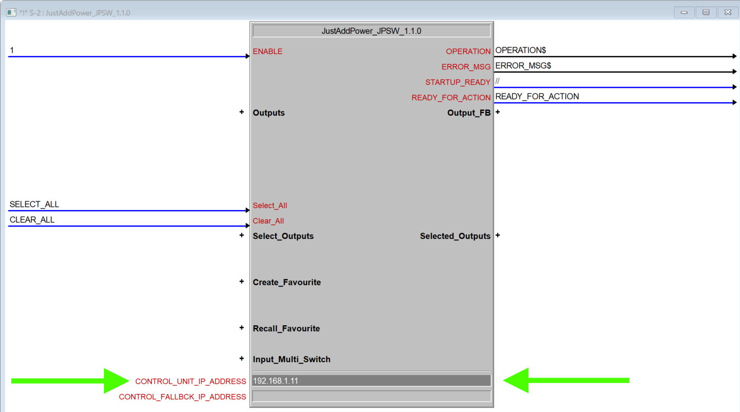
- Router WAN IP: 192.168.1.11
- (optional) Repeat the previous step for the each Endpoint Control or Feature Control driver, entering the same router WAN IP and changing the external WAN Port to match the targeted Just Add Power device
- Finished! The Secondary Control LAN thinks that it is talking to devices on the local network, but the communication is actually being routed through the Port Forwarded Router to the target device. No Default Gateway needed!

Use Primary LAN
This article describes an alternative way to build a Just Add Power system where it is connected to the unroutable secondary Control LAN on the processor.
The standard Just Add Power system is connected through the primary LAN port on the processor. If the Just Add Power switch is connected to the primary LAN port, all standard AMP VLAN rules apply, and a Static Route on the router provides control for Matrix, Feature, and Endpoint Control. This article is not needed.
