



Overview
When servicing an unfamiliar Just Add Power installation, the original system documentation may be unavailable, incomplete, or no longer reflect the equipment currently installed. Before making changes, gather information about the system hardware, switch connections, network settings, firmware, and control system.
This article provides instructions for locating and verifying each value requested by the Just Add Power Takeover Form. Record the information in the form as it is gathered to create a system record that can be used by the installer, Just Add Power Support, and future service technicians.
Recommended: Open or print the Takeover Form before beginning. Complete a separate switch entry for every switch carrying Just Add Power traffic, using the addendum on the second page when needed.
Before You Begin
- Confirm you have authorization to access the network, switches, and control system.
- Ask for any available project files, reports, network documentation, and login credentials.
- Photograph device labels, switch labels, cable labels, and switch-port connections before moving any cables.
- Record confirmed information in the Takeover Form as you work.
- Document any information that cannot be confirmed in the Additional Notes section.
Important: Do not reset a switch or change switch settings, firmware, IP addresses, or device connections until the existing system has been documented. These changes can interrupt service or remove configuration information needed to understand the installation.
Photos are useful for quickly capturing information, but they should support the Takeover Form rather than replace it. Transfer the confirmed values from the photos into the form before leaving the site.
Check for Existing Documentation
Look for an AMP or JADConfig Report File before gathering information manually. A Report File may contain:
- Switch model, management IP address, username, and password
- Number of Encoders and Decoders
- Switch-port assignments for VLAN systems
- Device IP addresses, subnet masks, and default gateways
- System configuration information available when the report was created
AMP Projects and Reports
On the PC used to configure or service an AMP system, locate the saved project and report information. If the project is available, AMP can also gather current information directly from an established system.
JADConfig Reports
If the original JADConfig PC is available, look for the report in the JADConfig Reports folder. Report filenames are based on the date and time the configuration was completed.
C:\Program Files (x86)\Just Add Power\JADConfig\Reports
Verify the report: A Report File documents the system at the time it was generated. Compare its device counts, switch connections, and installed hardware with the current installation because equipment or cabling may have changed.
Tools to Bring
Bring the tools needed to inspect the network, access the switches, and test the installed equipment. The exact requirements vary by switch model and system age.
Software
- Windows PC with a wired Ethernet adapter
- Advanced Matrix Programmer (AMP)
- JADConfig for servicing existing JADConfig installations
- Bonjour Browser
- PuTTY
- Docklight Scripting
- IPv4 discovery software, such as Advanced IP Scanner or Angry IP Scanner
Hardware
- USB-to-serial adapter and the appropriate switch console cable
- Just Add Power debug cable when serial access to a device may be required
- Known-working network and HDMI cables
- Headphones with a 3.5 mm connector
- A compatible spare power supply when devices are not powered using PoE
Gather System Details
Work through the following sections in the same general order as the Takeover Form. When a value can be obtained in more than one way, begin with existing documentation and then confirm it against the installed system.
Use the following sections to locate and verify each value requested by the Takeover Form. Select a category to jump to its instructions.
- Contact and Jobsite Information
- Control System
- Switch Information
- Data Network Connection
- Firmware Version
- Device IP Address
- Device Series
- Changes and Additional Notes
- Identify the System Type
- Complete the Takeover
Contact and Jobsite Information
Record: The first and last name, company, telephone number, email address, and jobsite name requested by the Takeover Form.
Use contact information for the person currently responsible for the service request and a jobsite name that clearly identifies the installation.
Control System
Record: The platform of the control system currently operating the Just Add Power installation.
Identify the control system by inspecting the equipment rack, control processors, touch panels, remote controls, and available programming documentation. Record the processor model when it is accessible and note whether the system appears to use an official Just Add Power driver, a third-party driver, or custom programming.
Just Add Power drivers and integration resources are listed on the Control System Drivers page.
Note: Record the control system currently operating the installation, even if older project documentation specifies a different platform. Also record whether the control processor communicates with the Just Add Power system over the network or through a serial connection to the switch.
Switch Information
Complete one switch entry on the Takeover Form for every switch carrying Just Add Power traffic. For each switch, record its manufacturer, exact model, hardware version when available, management IP address, login credentials, and connected Just Add Power devices.
Switch Model and Hardware Version
Record: The switch manufacturer, exact model number, hardware version, and the total number of switches in the system.
- Locate the manufacturer label on the switch.
- Record the complete model number exactly as shown.
- Record the hardware version when it is listed on the label.
- If the label is inaccessible, sign in to the switch management interface and locate the system or device information page.
- Repeat these steps for every switch carrying Just Add Power traffic.

Important: The switch model must match exactly. Also confirm the hardware version because switches with the same model number may use different hardware, firmware, or configuration requirements.
Compare the confirmed switch information with the configuration software support lists:
If a switch is not supported by JADConfig, it was not configured using JADConfig. If it is not supported by AMP Standardized, it was not configured using AMP Standardized. A switch that appears on a support list is only an indicator and does not, by itself, confirm which method was used.
Switch Management IP Address and Login
Record: The switch management IP address, username, password, available access methods, and whether login was confirmed.
Check the Report File and network documentation first. If the address is not documented, use one of the following methods.
Method 1: IPv4 Discovery Software
An IPv4 scanner can list the IP address, manufacturer, and MAC address of devices on the same network as the PC.

- Locate the switch MAC address on the manufacturer label.
- Connect the service PC to the Data Network.
- Open Advanced IP Scanner or Angry IP Scanner and scan the local IPv4 subnet.
- Match the MAC address on the switch label to a result in the scanner.
- Record the IP address shown for the matching result.

Method 2: Router Client List
Sign in to the jobsite router and locate its connected clients, DHCP leases, or network devices page. Match the switch MAC address or manufacturer to the client list, then record the corresponding IP address.

Method 3: Switch Console
If the switch cannot be located through documentation or network discovery, connect to its console port using the correct console cable and terminal settings for the switch manufacturer. Contact Just Add Power Support if assistance is required identifying the current management address.
Do not reset the switch: A factory reset removes the existing Just Add Power configuration and may interrupt every source and display connected to the system.
Verify Switch Access
After locating the management IP address and credentials, sign in to the switch and confirm that the management interface is accessible. Record any credentials that could not be verified.
Record the result: Finding a possible management IP address does not confirm switch access. Note whether the address responded and whether the supplied credentials were accepted.
Encoder Ports and Count
Record: The number of active Encoders connected to each switch, the first and last Encoder ports, any gaps in the port range, and any non-Just Add Power devices within that range.
- Inspect the cable labels and physical switch connections.
- Identify the ports connected to Just Add Power Encoders.
- Compare the connections with the Report File, switch port descriptions, or switch management interface when available.
- Record the total and port range on the Takeover Form.
- If the Encoders do not occupy a consecutive range, list the individual ports in Additional Notes and take a clear photo of the switch connections.
Decoder Ports and Count
Record: The number of active Decoders connected to each switch, the first and last Decoder ports, any gaps in the port range, and any non-Just Add Power devices within that range.
- Inspect the cable labels and physical switch connections.
- Identify the ports connected to Just Add Power Decoders.
- Compare the connections with the Report File, switch port descriptions, or switch management interface when available.
- Record the total and port range on the Takeover Form.
- If the Decoders do not occupy a consecutive range, list the individual ports in Additional Notes and take a clear photo of the switch connections.
Port order is a clue: AMP Standardized systems commonly place Decoders first, beginning on port 1, followed by Encoders. JADConfig systems commonly reserve port 1 for the Data Network connection, place Encoders next, and then place Decoders. Connections may have been moved after configuration, so confirm the system type using a Report File or switch configuration whenever possible.
- Switch Configuration Guidelines for AMP Standardized Systems
- Switch Configuration Guidelines for JADConfig Systems
- Multi-Switch Considerations for AMP Standardized Systems
Data Network Connection
Record: The switch port that connects the Just Add Power system to the general network or Data Network.
- Trace the network connection from the Just Add Power switch toward the router, core switch, control network, or other upstream network equipment.
- Check the cable label, switch port description, Report File, or switch management interface to confirm the connection.
- Record the port number and the equipment connected at the opposite end of the cable.
- For a system with multiple Just Add Power switches, repeat these steps on each switch.
Multiple switches: Distinguish the Data Network connection from links that carry Just Add Power traffic between switches. Record inter-switch connections in Additional Notes, including the port used on both switches.
If the service PC or control processor must communicate with devices on a separate Just Add Power Network, network routing may be required. See Setup a Static Route for an Established Just Add Power System.
Firmware Version
Record: The complete firmware version and build reported by the Just Add Power devices.
Use the method appropriate for the installed series:
- Review the device information in an existing Report File.
- Use Gather Details with AMP for an accessible AMP system.
- Open the device webUI or view the Decoder diagnostic screen.
- For Omega, Ultra, and MaxColor Series devices, follow How to Identify the Firmware Version of a Device.
- For 2G Series devices, follow How to Identify the Firmware Version for 2G Series Devices.

Check more than one device when the system contains different device series, models, or hardware versions. Record each firmware version and build that appears in the system.
Important: All Just Add Power devices in the system must be running compatible firmware. The required firmware version or build may vary by device series, model, and hardware version. Do not begin a firmware update until the installed hardware and current versions have been documented.
Device IP Address
Record: The IP address of at least one Just Add Power Encoder or Decoder, the device type, subnet mask, and default gateway when available.
Use one or more of the following resources to locate an address:
- Open the AMP Projects Folder and review the Report File.
- Gather Details with AMP.
- Follow How to Locate a Device IP Address.
- Use Bonjour Browser when the PC and device are on the same local network.
- View the device information on a Decoder diagnostic screen.
Avoid unnecessary service interruption: Do not disconnect an active source only to display a Decoder diagnostic screen unless the interruption has been approved. Begin with project documentation, AMP Gather Details, or network discovery.
After locating the address, use How to Access a Device if the device must be reached through the webUI, Telnet, or HTTP API.
Note: A device IP address helps identify the Device Network used by the system, but the address alone does not confirm how the system was configured. AMP network prefixes can be changed, and established systems may have been modified after their original configuration.
Device Series
Record: Every Just Add Power device series and model installed in the system.
Inspect the model number and product label on the Encoders and Decoders. When the labels are inaccessible, use the Report File, AMP Gather Details, device webUI, or Decoder diagnostic screen to identify the model. Check every applicable series on the Takeover Form.
Important: Do not identify the entire system from a single device. Confirm both Encoders and Decoders, including equipment connected to additional switches. Mixed-series systems exist and may have additional firmware or compatibility requirements.
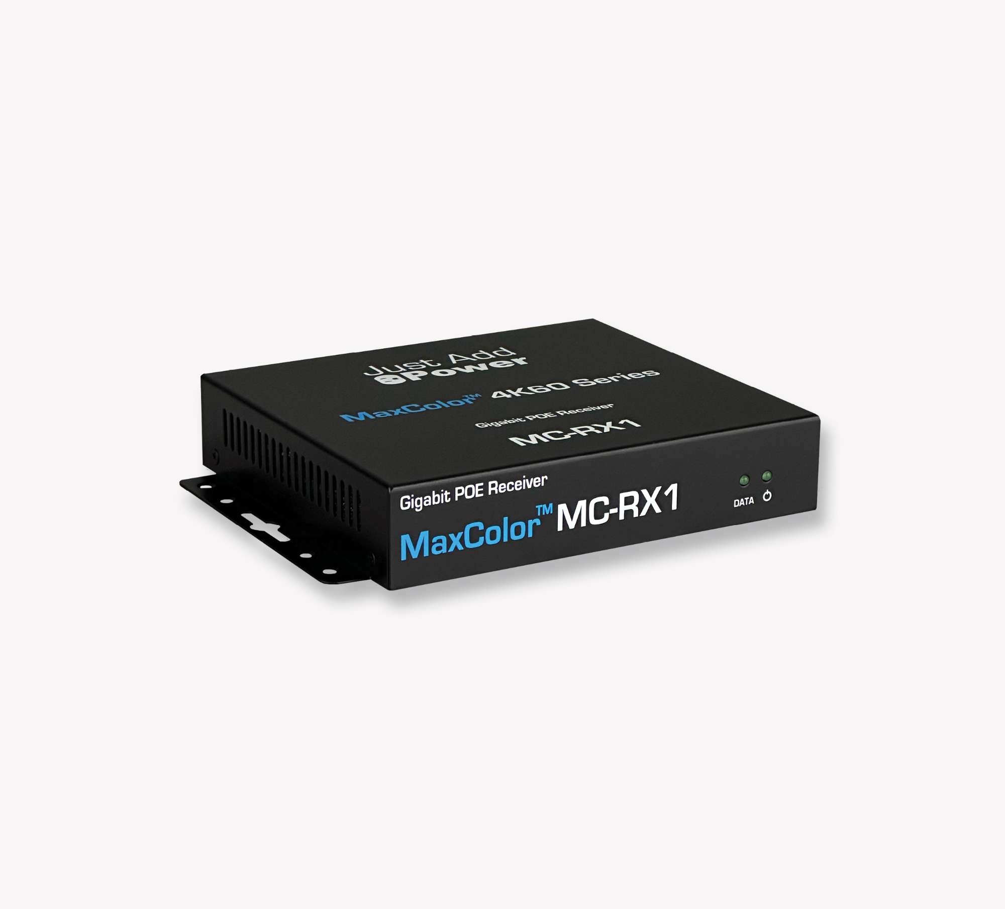
MaxColor Series
MaxColor Series products support 4K60, 36-bit color, and 4:4:4.
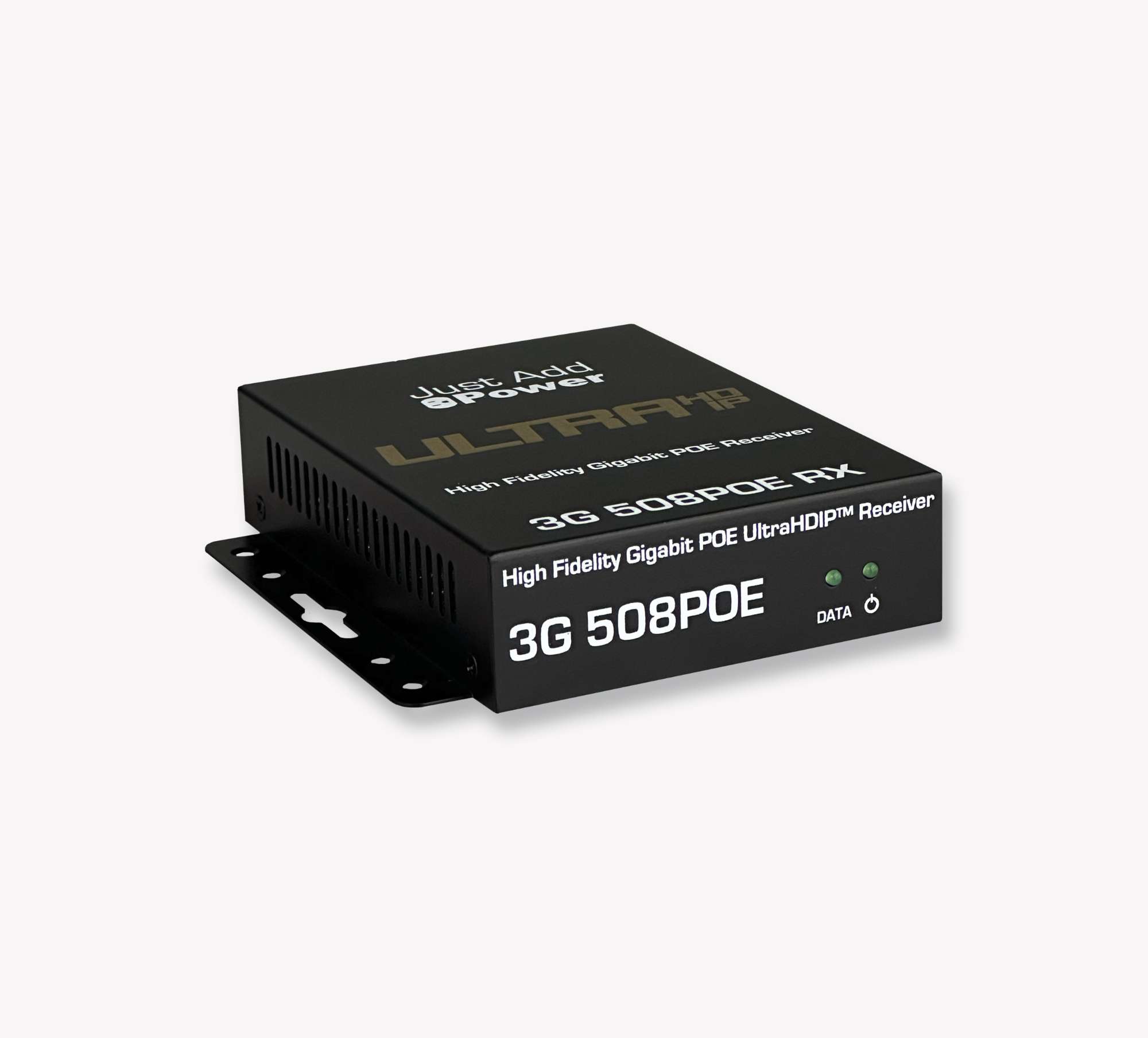
Ultra Series
Ultra Series products support video resolutions up to 4K30.
Omega Series
Omega Series products were developed as an upgrade to the 2G Series and can operate in supported Omega and Ultra Series systems.
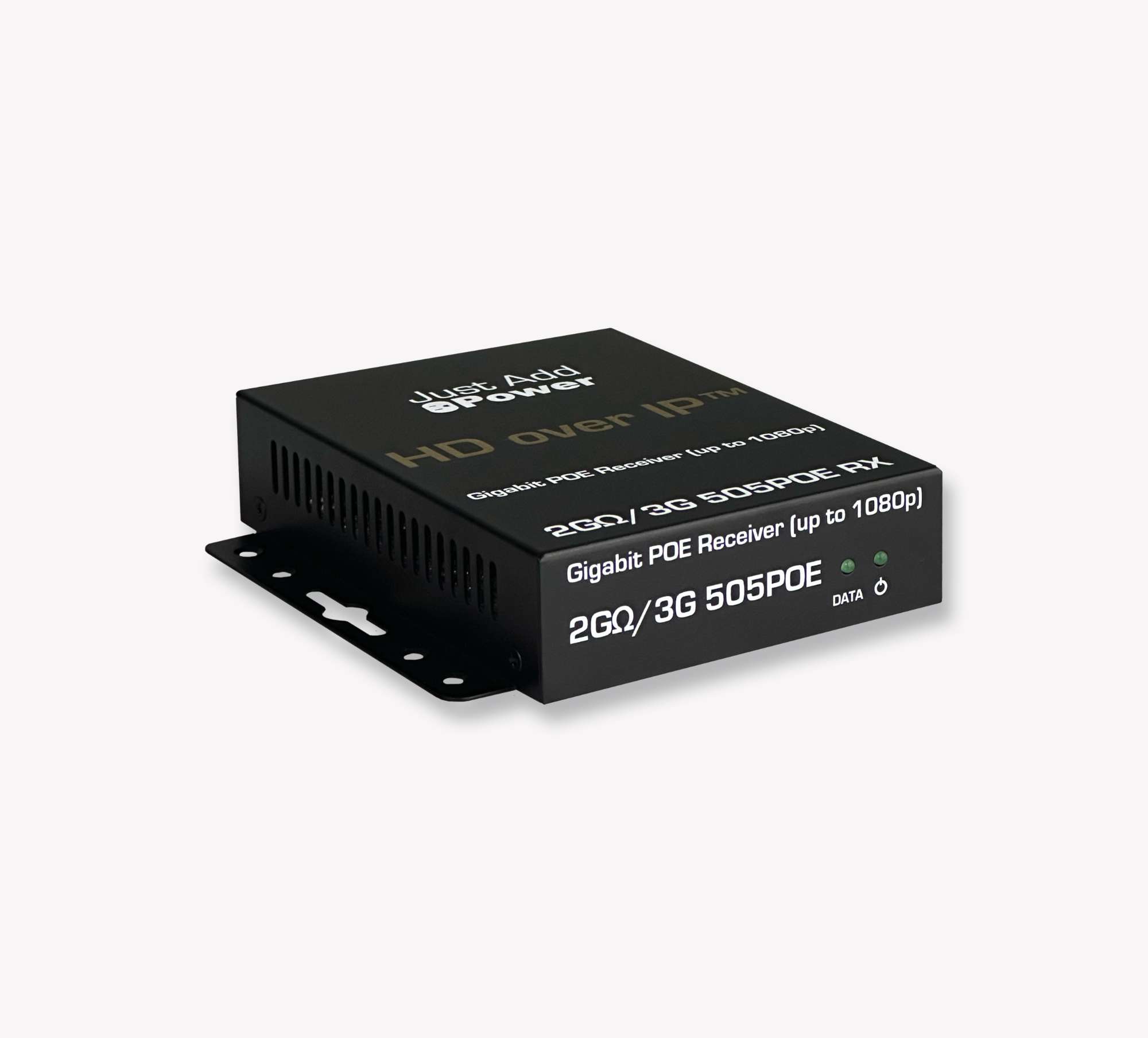
2G Series
2G Series products support video resolutions up to 1080p. Some 2G Series and Omega Series devices can operate together in supported legacy installations.

1G Series
1G Series products were designed for 1080p distribution over a 100 Mbps network. Contact Just Add Power Support when taking over a system that contains 1G Series hardware.

Changes and Additional Notes
Record every change made after taking responsibility for the system, including:
- Moved or replaced network connections
- Changed switch settings, management addresses, or login credentials
- Changed Just Add Power device IP addresses
- Updated device firmware
- Replaced Encoders, Decoders, power supplies, or switches
- Changed control system programming or drivers
Use the Additional Notes section to document nonconsecutive switch ports, mixed device series, inter-switch connections, inaccessible equipment, third-party network devices, or any value that could not be confirmed.
Recommended: Before making a change, take a photo or export a backup when the equipment supports it. Record the original value, the new value, the reason for the change, and the date.
Identify the System Type
After gathering the requested values, compare the Report File, switch model, switch configuration, device addressing, and port arrangement to identify the likely configuration method.
For an overview of the two current AMP configuration methods, see Choosing Between Standardized and Alternate Configurations.
Important: IP addressing and switch-port order are supporting clues. Neither one confirms the configuration method by itself. Use an AMP or JADConfig Report File, recognizable switch configuration, or original project information whenever possible.
System Type Indicators
| Evidence | What It May Indicate | How to Confirm |
|---|---|---|
| AMP project and Report File match the installed equipment | AMP Standardized or AMP Alternate | Open the project in AMP and compare the project type, switch information, and connected devices. |
| JADConfig Report File matches the switch and port assignments | JADConfig | Compare the report with the current switch model, device count, and physical port connections. |
| Decoders begin on port 1 and are followed by Encoders | Common AMP Standardized port layout | Confirm with the AMP project, Report File, or switch VLAN configuration. |
| Port 1 connects to the Data Network, followed by Encoders and then Decoders | Common JADConfig port layout | Confirm that the switch is supported by JADConfig and compare the connections with a JADConfig Report File. |
| No consistent Encoder and Decoder port grouping | AMP Alternate or a custom multicast configuration | Review the switch multicast configuration and look for an AMP project or other original documentation. |
| Control processor connects directly to the switch using serial | Custom Serial Control | Review the control system programming and switch console connection. |
System Types
| System Type | Configuration Method | Supported Series | Current Status |
|---|---|---|---|
| AMP Standardized | VLAN switching configured using AMP | Omega Series Ultra Series MaxColor Series |
Supported |
| AMP Alternate | Multicast switching configured using AMP | Omega Series Ultra Series MaxColor Series |
Supported |
| JADConfig | VLAN switching configured using JADConfig | 2G Series Omega Series Ultra Series |
End of Service January 1st 2027 |
| Custom Multicast | Manually configured multicast switching | 2G Series Omega Series Ultra Series |
Limited support |
| Custom Serial Control | Custom switch configuration controlled through a direct serial connection | 1G Series 2G Series |
Contact Just Add Power Support for evaluation |
Existing JADConfig systems: JADConfig remains available for servicing established installations. New systems and expansions should be configured using AMP after compatibility and conversion requirements have been evaluated.
If the available evidence does not identify the configuration method, do not guess. Record the evidence collected and contact Just Add Power Support for assistance reviewing the system.
Complete the Takeover
- Review every field on the Takeover Form and mark any value that could not be confirmed.
- Verify the device counts and port assignments against the installed equipment.
- Attach clear photos of switch labels, switch connections, device labels, and diagnostic screens.
- Attach any available AMP or JADConfig Report Files.
- Save a copy of the completed form with the jobsite documentation.
- If assistance is needed, email the completed Takeover Form to Just Add Power Support.
Complete: The takeover record should allow another technician to identify the installed hardware, access each switch, understand the network connections, locate the Just Add Power devices, verify firmware compatibility, and recognize the control method without repeating the site survey.

