


Just Add Power System Takeover Guide: Identification, Inventory, and Documentation
Overview
Use this guide to take over an unfamiliar Just Add Power system. First identify its configuration from existing records and installed-system evidence. For a confirmed AMP Standardized Configuration or AMP Alternate Configuration system, use the matching Gather Details workflow to generate a fresh report.
For a confirmed AMP system, use Gather Details to generate a fresh Report File. Submit that file instead of completing the Takeover Form. Include a brief problem description and known missing equipment or discrepancies. When a fresh report cannot be supplied, use the Takeover Form to summarise the system, available access, and unresolved issues. For an identified JADConfig system being prepared for migration, use the Migration Form as the detailed connection map and reference it in the takeover summary.
JADConfig End of Support: January 1, 2027. Beginning on that date, a system must be migrated to AMP before the Just Add Power Support Team can provide further troubleshooting or system service. JADConfig-related support-site articles, documentation, downloads, and drivers are scheduled for removal beginning on that date. See the JADConfig End of Support Notice.
End of Support does not disable an existing system. The survey below preserves the information needed to plan its next steps without relying on JADConfig availability.
Before You Begin
- Confirm access to the jobsite, equipment, network administrator, and control system programmer.
- Record the reason for the takeover and the system's current condition. Identify which sources and displays work, which fail, and whether switching or endpoint control is affected.
- Recover available reports, port maps, and site records. Use a fresh AMP Report File for a confirmed AMP system. Otherwise prepare the Takeover Form as a summary; retain any existing inventory or completed Migration Form so connections do not have to be recorded twice.
- Take an overview photograph of the rack and existing connections before touching the wiring. Collect detailed device and port photographs as needed after identifying the system type.
- Agree on any interruption needed to access concealed equipment or display a diagnostic screen. Begin with checks that leave the operating system connected.
Preserve the existing configuration: Do not factory reset equipment, upload switch configuration files, execute AMP Build New, update firmware, change addresses or VLANs, or move device, uplink, or stack connections during the survey. Those actions belong to a separately planned service or migration procedure.
For each value, record where it came from and whether it was verified on-site. Keep old report values separate from current observations when they disagree. Store credentials in the jobsite's protected service records; avoid exposing them in general photographs or shared examples.
First, Identify the System Type
Before tracing every device or manually collecting addresses, check whether the installation uses AMP Standardized Configuration or AMP Alternate Configuration. Ask the owner, previous installer, or service technician how it was configured and whether it has been migrated since its original installation. Record the type as Confirmed, Suspected, or Unknown, with the supporting evidence.
Look for a jobsite-specific AMP project or Report File on the original service PC or in the site records. Check its configuration type, switch identity, and a sample of installed devices or port connections. You do not need to complete the full physical inventory to make this initial comparison. See AMP Projects and Reports for the folder location and access steps.
If records are missing, inspect a small sample of readily accessible switch connections and ask the programmer or network administrator to inspect the existing control project and switch configuration. Use the indicators below together. An AMP installation on a service PC, an IP address pattern, a supported switch, device firmware, or port order alone does not establish how this jobsite was configured. See Standardized and Alternate Configurations for the differences.
Keep identification and access separate: A confirmed AMP system may still be unreachable. If the type is unclear, use only the switch access, network connection, or device address checks needed to obtain more evidence, then return here. You do not need a complete manual inventory before checking for AMP.
System Type Indicators
Inspect existing records and settings without changing them. Port patterns describe assigned ports; empty reserved ports, later changes, and unresolved cable destinations can obscure the visible order.
| Evidence | Possible Interpretation | What to Check Next |
|---|---|---|
| Jobsite-specific AMP project or report identifies Standardized or Alternate Configuration | Evidence of an AMP installation | Compare the date, device identities, network settings, and a sample of connections with the current installation. Check for a later migration or replacement. |
| Decoder ports begin at port 1, Encoder ports follow, and the designated network uplink is the last RJ-45 port of the single switch or Switch 1 | AMP Standardized port pattern | Compare the records and actual assignments with AMP Standardized switch configuration guidelines. Check a sample rather than tracing every endpoint first. |
| Switch configuration contains the expected AMP VLAN structure, including system VLAN 100 and source VLANs beginning at 101 | Additional evidence of AMP Standardized Configuration | Compare device-port membership with How VLAN Switching Works. Retain the existing configuration; VLAN numbers alone are not proof. |
| Data Network on port 1, followed by Encoder ports and then Decoder ports; legacy switch configuration uses Decoder VLAN 10 and source VLANs beginning at 11 | Common JADConfig pattern | Compare any saved JADConfig report with the current switch and connections. A historical report does not rule out a later AMP migration. |
| Devices share a dedicated VLAN and source selection uses Decoder Channel assignments | Multicast Switching, which may be AMP Alternate or manually configured | Look for a matching AMP Alternate project/report and inspect existing network and device settings with the administrator. Multicast Switching supports both AMP and manual setup; the switching method alone does not establish AMP history. |
| Older 2G Series hardware uses a single-VLAN multicast design | A possible legacy multicast installation | Record the exact hardware and existing settings. Do not classify it as AMP Alternate: AMP 2G Legacy Mode requires Standardized Configuration. |
| Several switches share one management interface and use stack-member IDs, or have separate management interfaces and trunk links | Clues about the network topology | Use Stacking vs Trunking to identify members and links. The topology alone does not establish configuration history. |
| Control project identifies a switching driver, command target, or serial connection | Evidence of how sources are controlled | Ask the programmer to verify the installed driver and target. A generic device or endpoint-control driver, or a serial cable alone, does not establish the configuration type. |
If the property contains separate matrices or networks, identify each independently. Do not combine devices from different systems into one inventory solely because they share a rack or building.
Choose Your Takeover Path
| Identification Result | Next Action |
|---|---|
| AMP Standardized Configuration | Use Standardized Gather Details. Generate a fresh Report File and submit it instead of completing the form. Include supported systems already operating in AMP 2G Legacy Mode. |
| AMP Alternate Configuration | Use Alternate Gather Details. Generate a fresh Report File and submit it instead of completing the form. |
| JADConfig or another identified non-AMP configuration | Complete the takeover summary from available records and relevant manual checks. For an identified JADConfig system proceeding to AMP, use the Migration Form as its detailed port map. Other or custom systems use an appropriate current connection record; do not apply the JADConfig template by assumption. |
| Suspected AMP or Unknown | Continue the minimum identification and access checks. If the type remains unresolved, use the manual form and record it as Suspected or Unknown. Do not attempt report generation merely to decide whether it is AMP. |
| AMP identified, but Gather Details cannot complete | Identify the Just Add Power switch management IP and the actual Device Network subnet and mask. AMP defaults to 172.27.0.0/16 and supports 172.20.0.0/16 through 172.29.0.0/16. Verify the service-PC route using the installed values, then retry Gather Details. For unresolved access or retrieval problems, keep the confirmed AMP identification and complete the manual form. |
Gather Details for an Existing AMP System
Use this section only after the installed system has been identified as AMP Standardized Configuration or AMP Alternate Configuration. Do not use retrieval failure as an identification test. Preserve recovered files and save the fresh report separately for comparison; the original configuration PC is not required for retrieval from your service PC.
Establish a wired connection and the correct network path first. Use a documented device address where available. If the connection or address is unknown, complete the relevant network connection and device address checks, then return to the appropriate workflow below. Keep devices connected to their assigned ports.
AMP Standardized Configuration
- Connect the service PC through a verified Data Network connection. Confirm the network path to an existing Encoder or Decoder, including any required routing.
- Open AMP and select Service > Gather Details.
- Follow Gather Details with AMP to retrieve the current system information and generate a Report File containing IP addresses, device counts, and port connections.
- Save the new report with the takeover records, then continue to Review the Gathered Information.
AMP Alternate Configuration
- Connect the service PC using a wired adapter and confirm access to the established devices through the site's existing VLAN and routing design. Have the network administrator verify the connection if needed.
- From the AMP start screen, select Alternate Configuration in the lower-left corner and acknowledge the disclaimer.
- Open Gather Details from the Alternate Configuration service options and follow its prompts to gather the available system information.
- Save the available results with the takeover records. Continue to Review the Gathered Information and obtain any missing switch, port, and network details from the administrator or manual inspection.
Alternate Configuration uses a separately managed multicast network. Do not assume its results include the same switch inventory or port mapping as a Standardized report. The linked Standardized video demonstrates a different entry path.
Review and Save the AMP Report
A fresh AMP report replaces the Takeover Form. Save the report and use it as the system record. If assistance is needed, submit it with a brief problem description and the existing ticket number.
- For Standardized Configuration, use the report's switch-configuration information to establish configured Encoder and Decoder counts. Compare those assignments with devices retrieved and equipment expected on-site. Do not treat configured counts as proof that every device is connected or present.
- Review reported link activity and fields marked with question marks. Record which entries could not be fully read or contacted. A question mark is not, by itself, proof that the device is physically missing.
- Identify known missing, disconnected, replaced, or inaccessible equipment and any differences between the report and the installation. Include those items in the problem description or a short attached list.
- For Alternate Configuration, review the available device results and obtain missing switch or physical-port information from existing network records when relevant. Do not assume identical report fields across the two workflows.
Report generated: Skip the manual form and full manual survey. Use only the targeted checks needed to explain a discrepancy or problem, then continue to Complete the Takeover.
A generated report can document a system with faults. Poor network links, question marks, or unresolved entries do not automatically require a duplicate manual form.
Check for Existing Documentation
Ask the owner, previous installer, network administrator, and control system programmer for existing reports, project files, cable schedules, network diagrams, switch configuration backups, and control system programming. Copy the available records before changing the installation.
A report may contain switch management settings, device addresses, device counts, and port assignments. Check its date and compare it with the installed hardware. A saved report describes the system when the report was created.
AMP Projects and Reports
- On the PC previously used to configure or service the system, open AMP.
- Select the top-left menu, then File > Open Projects Folder.
- Locate the jobsite's project and Report File. Preserve a copy and compare the switch and endpoint inventory with the installation.
The usual location is C:\Users\[YourUsername]\Documents\Just Add Power\AMP\Projects. See Open the AMP Projects Folder if the folder is unavailable or redirected.
If the records identify AMP Standardized or AMP Alternate Configuration, use the applicable Gather Details workflow before completing the manual inventory. A missing project folder on your own PC does not show how the jobsite was configured.
Recover records without reconfiguring: A saved project may describe configuration work that was never completed. Compare it with the current installation and retrieved information. Do not load an unfinished configuration workflow or execute Build New to test the system identity.
JADConfig Reports
Recover existing reports as files. You do not need to launch JADConfig to locate or read a saved report.
- On the original configuration PC or its backup, open File Explorer.
- Check
C:\Program Files (x86)\Just Add Power\JADConfig\Reports. If it is missing, ask for a backup or previously exported copy. - Check the report date and compare its switch models, device counts, and port assignments with the installed system.
- Keep the original report with the survey and record any differences in the Takeover Form.
If no report exists: Continue with the physical inventory below. Do not delay the survey to obtain JADConfig, and do not reset equipment to recreate a report.
Preserve Switch Configuration Backups
If switch login is available, export a backup before any planned service changes. Use the instructions for the installed manufacturer and interface:
- Luxul: download a switch configuration
- Netgear M4250: download through the AV webUI or Main webUI
- TP-Link JetStream: download a switch configuration
- Cisco CBS350: download a switch configuration
Record the switch identity, firmware, export date, and configuration type. Where available, preserve both running and startup configurations: running settings may include changes not saved for the next boot. Do not save, overwrite, upload, or reboot the switch merely to make the files match. Use manufacturer instructions for other models.
Store backups in protected jobsite records because they can contain credentials and network details. A backup preserves configuration evidence; it does not by itself confirm source/display mapping or compatibility with another switch model.
Tools to Bring
Bring a Windows PC, a wired Ethernet adapter, labels, a camera, and access to the Takeover Form. Prepare the following tools as needed for the installed equipment.
Software
- Advanced Matrix Programmer (AMP) for established AMP workflows and the planned migration.
- Bonjour Browser for supported devices reachable on the same local network.
- PuTTY for supported terminal access.
- IPv4 discovery software approved for use on the site's network.
- Switch manufacturer documentation for the exact model, including console cable and terminal settings.
JADConfig is not required for this survey. Retain any existing jobsite reports and configuration backups.
Hardware
- USB-to-serial adapter and the appropriate switch console cable
- Just Add Power debug cable when serial access to a device may be required
- Known-working network and HDMI cables
- Headphones with a 3.5 mm connector
-
A compatible spare power supply when devices are not powered using PoE:
Bring labels for both ends of each network cable. Use only a power supply appropriate for the exact device model.
Record the Takeover Information
Use this section when you cannot supply a fresh AMP Report File: the system is non-AMP, its type is unresolved, or a confirmed AMP system has access or retrieval problems. The Takeover Form records the system's identity, condition, available network/device information, and assistance needed. Keep the identified configuration separate from the retrieval problem.
Use recovered records and the relevant checks below to complete the summary. Enter Unknown, Inaccessible, or Not present where appropriate, with a short reason. Do not recreate verified information already held in an attached record; identify that record and the relevant switch or device instead.
If these checks confirm AMP, use its Gather Details workflow to generate a fresh Report File and submit it instead of continuing the form. For an access or retrieval problem, retain the confirmed AMP identification and record the limitation.
Contact and Jobsite Information
Record the service contact, company, telephone/email, jobsite, and survey date or ticket number. Use the same jobsite reference on the summary and its attachments so Support can associate them. Where an attached completed record already supplies the contact details, reference it rather than copying the complete contact block again.
Control System
Record: The control platform, processor model, programmer contact, project availability, installed switching driver or plugin, and its connection target.
- Identify the control processor in the rack and compare it with the project documentation.
- Ask the programmer to identify whether switching uses an official Just Add Power driver, a third-party driver, or custom programming. Record the driver name and version when available.
- Record whether commands target a switch or a Just Add Power device, the configured IP address, and whether the connection uses Ethernet or serial.
- Record which source and display names correspond to each Encoder and Decoder. Include IR, RS232, CEC, audio, USB, or other connections that must be preserved.
- Confirm who can supply and update the control project. Mark driver details as Unknown if the project cannot be inspected.
Review Control System Drivers for integration resources. Prepare driver changes as part of migration planning; leave the active control program in place during the survey.
Use the Takeover Form's Control System field for the platform. Add the programmer contact, available project/driver information, and relevant endpoint-control details in its summary notes or existing control records. The Migration Form's port map does not replace this control-system context.
Device Series
Read the exact model label on every Encoder and Decoder. Record the model, labeled MAC address, physical location, and whether it is an Encoder or Decoder. Compare labels with accessible device information where possible.
For older enclosure labels or remotely reported models, use Identify a 2G Series Model or Identify an Omega Series or Ultra Series Model. Apply command-based methods only where the article supports the installed firmware. Hardware series alone does not identify the configuration software.
Check every installed series on the form. A product photograph helps recognize hardware, but the label and exact model identify it. Devices with similar enclosures can have different capabilities.
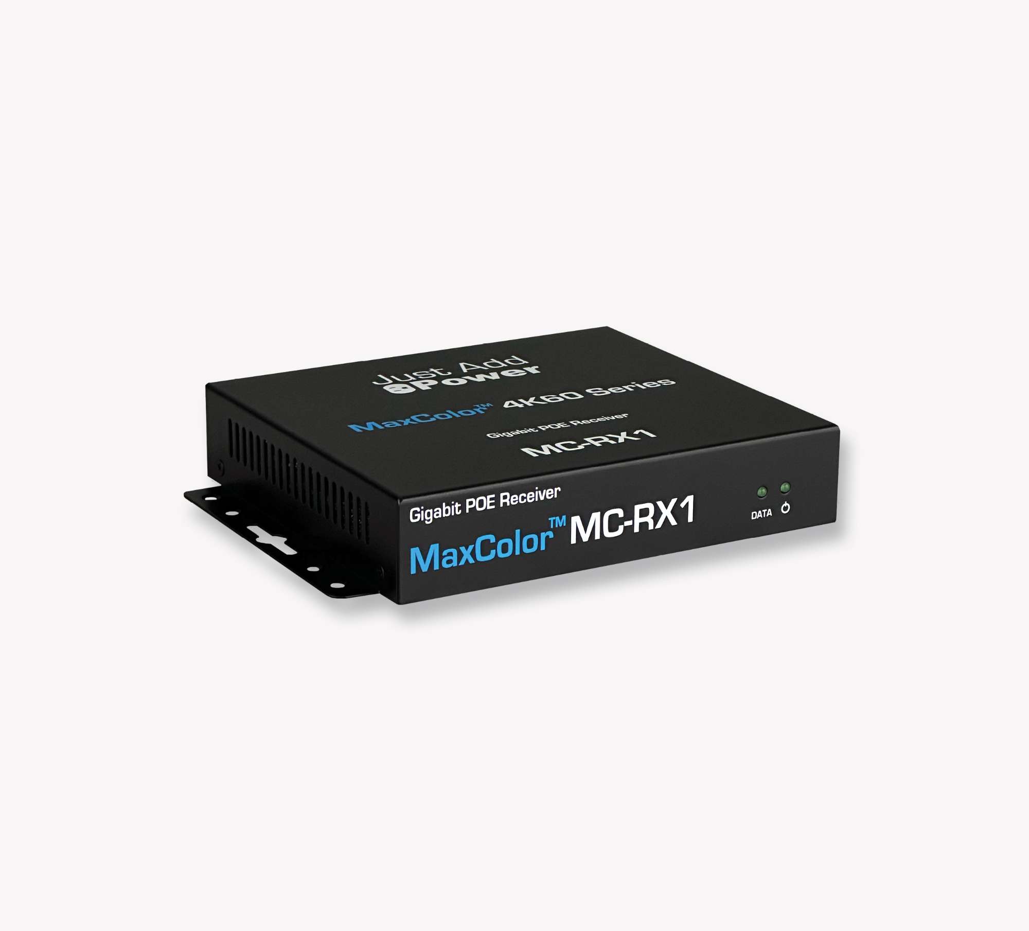
MaxColor Series
Record the full MaxColor model from the label, including any suffix. Keep its firmware and connection information separate from other installed series.
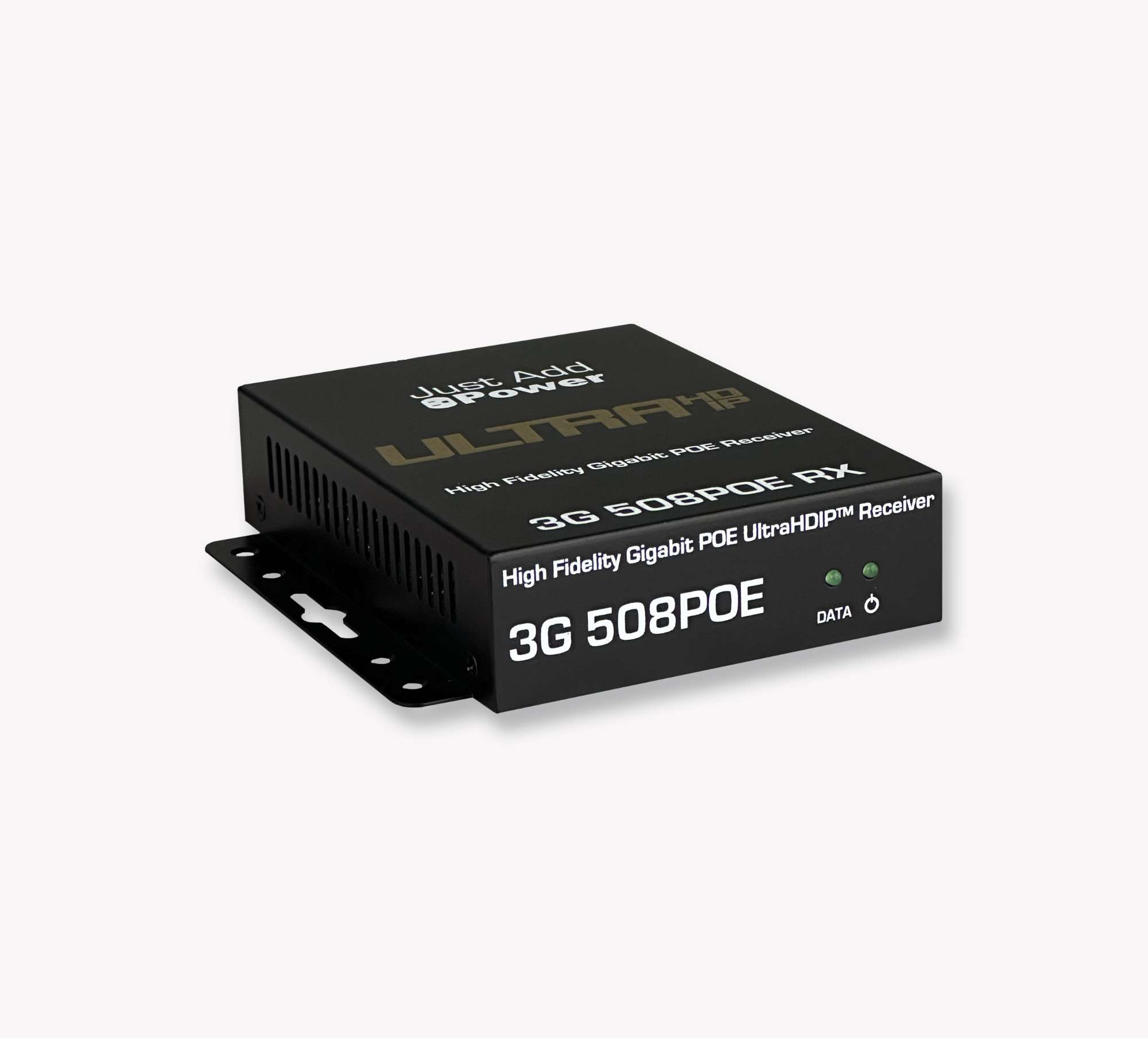
Ultra Series
Record the exact Ultra Series model. If the installation also contains 2G Series devices, check model-specific 2G Legacy Mode compatibility before planning migration.
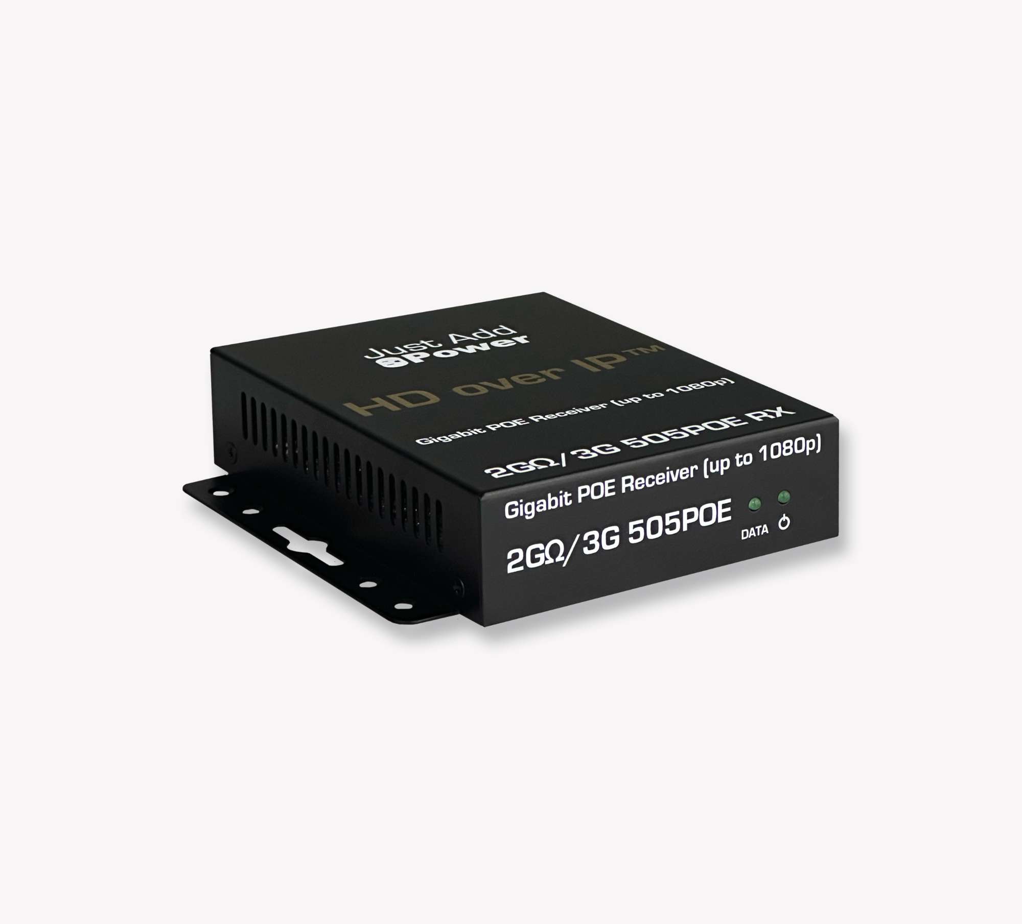
Omega Series
Record the exact Omega Series model. Older records may describe Omega hardware as 2G/3G; preserve that original label alongside the verified model.
2G Series
Record each 2G Series model. AMP supports eligible systems through 2G Legacy Mode in Standardized Configuration. Review the exact hardware mix and limitations before planning the transition.

1G Series
Identify and record 1G Series hardware separately. Do not assume it can be included in an AMP configuration; request an evaluation of the required replacement path.

Switch Information
Identify every switch carrying Just Add Power traffic and use a consistent switch ID/location. If a completed Migration Form or another verified map already records its model and connections, reference that entry in the takeover summary. Use the form's switch block and additional-switch page only for details not already covered. Keep temporary survey labels separate from any future AMP switch assignment.
Switch Model and Hardware Version
- Read the manufacturer label and record the complete model number, hardware version, serial number, and labeled MAC address.
- If the label is inaccessible, check the system information page through an existing management connection. Record the switch firmware version when available.
- Photograph the label and the port numbers. For a stack, identify each physical member rather than recording only the shared management address.
- Repeat for all switches and record the total switch count.

For AMP Standardized migration planning, compare the exact model and hardware version with Supported Switches for AMP Standardized Systems. For multiple switches, also review Multi-Switch Considerations.
Compatibility and identification are separate checks: A current support list determines suitability for the planned AMP system. It does not prove how an older installation was configured. Preserve the installed configuration and available reports as evidence.
Switch Management IP Address and Login
Record: The management IP address and subnet mask when available, access method, and whether the supplied login was accepted. A responding IP address is not proof of a successful login.
Start with the report, network records, and control project. Connect the service PC to a known Data Network connection, then check the methods below.
Locate the Switch Address
- Record the PC's wired IPv4 address, subnet mask, and default gateway. In Windows, execute
ipconfigin Command Prompt to view the adapter settings. - Ask the network administrator to check the router's client list, DHCP leases, reservations, and network records for the switch. A statically addressed switch may not appear in the DHCP lease list.
- If the switch is not documented, scan the authorized local IPv4 subnet using an approved discovery tool. Compare a result with the switch's labeled MAC address and model; a manufacturer name alone is insufficient.
- Open the candidate address in a browser and verify the switch identity and login. Record any address or credentials that remain unconfirmed.


No result does not mean no switch: A scan covers only the selected address range and reachable networks. A different management subnet or VLAN, filtering, or an incorrect PC connection can prevent discovery. Ask the network administrator to verify the management network before changing anything.
If Network Access Is Unavailable
- Check whether the exact switch has a console port and obtain its manufacturer-specified cable and terminal settings.
- Use the manufacturer's documented display-only procedures to inspect the current management settings and system information, if the available credentials permit access.
- Record the result. If access cannot be established, mark the management address or login as Unknown and continue the physical inventory.
Do not use password recovery, reboot, factory reset, or configuration commands to complete this survey. Missing credentials can be addressed during a planned migration after the required connection mapping has been recorded.
During takeover, record useful identity and access facts even when a switch may later be replaced. The Migration Form requests management information for retained switches as part of transition planning; that does not establish that such information is unnecessary for identifying or accessing an unfamiliar system. Keep credentials in protected service records and arrange any required credential handoff securely.
Encoder Ports and Count
Inventory each installed Encoder, including disconnected or unpowered units. Distinguish the installed count from the powered or reachable count.
- Starting at the lowest connected Encoder port on the current switch, trace the network cable through any patch panel to the Encoder. Record intermediate panel labels.
- Record the device model, labeled MAC address, physical location, connected source, switch identifier, and full port designation.
- Match the physical connection with existing cable labels, port descriptions, or a switch MAC address table when available. MAC entries learned through an inter-switch link do not identify the endpoint's local port; continue tracing on the downstream switch.
- Label the device and its cable consistently without removing useful existing labels. Record every network connection for devices that use more than one switch port.
- Record the installed Encoder count and its switch connections. Use the completed migration map or existing verified list as the detailed record. On the takeover summary, reference that map; enter count/first-last ports only where they are not already supplied. Add an exact port list for gaps or additional connections.
A link LED confirms a link, not the identity of the device. An empty or dark port is not proof that no installed device belongs there. Mark unresolved cable destinations for follow-up.
Decoder Ports and Count
- Starting at the lowest connected Decoder port on the current switch, trace each connection through any patch panel to the Decoder.
- Record the device model, labeled MAC address, physical location, connected display or destination, switch identifier, and full port designation.
- Record associated control, audio, USB, and video-wall connections or assignments when present.
- Label the device and cable consistently. Include unpowered or disconnected Decoders and identify their condition separately.
- Record the installed Decoder count and its switch connections. Reference a completed migration map or existing verified list instead of copying it into the takeover summary. Use the summary's count/first-last ports where no attached record supplies them, and identify any gaps or extra connections.
Keep the current device order and control-system names in the inventory. Do not move cables to make the existing installation match an expected port pattern. The migration preparation guide supplies the E1/E2 and D1/D2 labeling sequence when a JADConfig system is being prepared for AMP.
Data Network Connection
- Trace the existing connection from the Just Add Power switch toward the router, core switch, or control network.
- Record the port and equipment at both ends. Compare the physical connection with port descriptions, the report, and network documentation.
- For multiple switches, record every inter-switch link and stack connection separately, including the port at each end, cable type, and physical stack-member identifiers.
- Record the router model, relevant network subnets, and existing routing information when available from the network administrator.
Verify the service-PC connection: An unused port may already be assigned to an Encoder or Decoder VLAN. Connect through a verified Data Network access point. Do not disconnect an endpoint, change VLAN membership, or break a stack to gain access.
If device access requires routing, first confirm the actual Device Network, subnet mask, and next-hop address from the installed configuration or network records. Then follow Static Routing for an Established Just Add Power System with the network administrator. Do not guess routing values from an IP-address pattern.
Working control does not establish PC access: The control processor may use its own gateway or a different permitted network path. That does not provide routing for the service PC. Verify access from the PC itself. For Alternate Configuration, use the site's actual inter-VLAN router or Layer-3 switch as appropriate; do not assume an AMP Standardized switch gateway.
Device IP Address
Identify one Encoder or Decoder and record its role/name or location with its observed IP address. The Takeover Form asks for this identified device first, followed by that device's firmware. Add the actual Device Network and subnet mask/prefix to the switch summary where known. Reference an attached record for additional verified addresses; do not invent values from a default address pattern.
Begin with a saved report or the control project's endpoint settings. Treat saved addresses as unconfirmed until matched with the installed equipment.
Check Local Discovery Where Available
For Omega Series, Ultra Series, and MaxColor Series devices on the same local network as the service PC:
- Open Bonjour Browser and expand Web Server (HTTP).
- Select a device and record the displayed address and service name.
- Match it to the physical device using the label and MAC information when available. See Bonjour Browser Device Discovery.
Bonjour discovery does not normally cross VLAN or routed boundaries. An established VLAN system's endpoints may not appear from the Data Network even when video works. Do not change VLANs or move endpoints to make them discoverable. This procedure does not assume Bonjour support on 2G Series or 1G Series hardware.
Read a Decoder Diagnostic Screen
A diagnostic screen can provide a Decoder address without first establishing a network connection. Use an existing diagnostic screen if one is already visible.
Confirm the interruption first: Removing an Encoder's HDMI input interrupts that source for every destination currently viewing it. Agree on an appropriate source and service window before performing the following steps.
- Identify a display connected to a Decoder and the source it is currently viewing. Record the original source selection.
- Locate the Encoder for that source and disconnect only its HDMI input cable. Leave power, network cables, and switch connections in place.
- Wait for the diagnostic screen. The documented procedure for 2G Series, Omega Series, Ultra Series, and MaxColor Series describes a wait of approximately 10 seconds; the screen layout depends on the installed firmware.
- Photograph the full screen. Record the Decoder's Local IP or RX IP and any model, firmware, or date information shown.
- Reconnect the same HDMI cable and verify that the affected destinations return to their previous operation.
The Local/RX field identifies the Decoder. A Remote/TX field can show the last Encoder viewed; do not use that field alone to identify the current Encoder.
If a diagnostic screen does not appear or the required fields are absent, record the result. Do not reset the device or change its settings to force the screen. See Locate a Device IP Address for Omega Series, Ultra Series, and MaxColor Series, and use the 2G guidance in the firmware section below for older hardware.

Verify Access to the Identified Device
After establishing the correct network path, open the device address in a browser using the interface supported by that model and firmware. Compare the displayed identity with the physical inventory and record whether access succeeded. Use Access a Device for Omega Series, Ultra Series, and MaxColor Series, or Access a 2G Series or 2G Legacy Mode webUI for older hardware.
If the system is identified as AMP Standardized or AMP Alternate Configuration, return to its Gather Details workflow before manually collecting the remaining information. If identification or retrieval remains unresolved, continue the manual survey and record the uncertainty.
If access fails, record the PC connection, the observed device address, and the method attempted. A visible diagnostic address does not establish reachability. Continue documenting physical connections instead of changing addresses or starting a configuration workflow.
Firmware Version
Record: The complete version string, build or displayed firmware date, device model, and the method used to obtain it. Identify which device each value belongs to.
- Omega Series, Ultra Series, and MaxColor Series: View the firmware information in the device webUI, diagnostic screen, or an applicable AMP inventory. See Identify the Firmware Version of a Device.
- 2G Series: On a reachable device, open System > Version Information in its webUI. If only the diagnostic screen is available, record the complete displayed date and a photograph. Do not invent a version number from the date.
- Other or inaccessible hardware: Record the exact label, any displayed version information, and what remains unknown.
Record each version encountered, especially after hardware replacements or where multiple series are installed. A report's firmware entry remains historical until checked against the current device.
Check compatibility before updating: Compatible firmware is required, but version strings may differ by series, model, and operating state. Do not assume every device must carry the same version string. Leave firmware unchanged during this survey; use the applicable AMP compatibility workflow during the planned transition.
Associate the form's firmware answer with the identified device in the preceding IP-address answer. Record other observed versions and their device identities in notes or the existing device record, especially where the installation contains mixed hardware or replacements.
Changes and Additional Notes
Use the form's System identification, access problems, current issue and changes made area to record the configuration and evidence, the present problem, retrieval/access limitations, programmer contact where relevant, and any changes already made. Keep uncertain identification explicit.
Use Supporting records / migration map reference / missing equipment / other notes to name the attached port map, historical report, photographs, or backups and identify the relevant switch/device. Include missing/offline equipment, unresolved connections, and disagreements between records and current observations.
A completed migration map already provides the current source/display-to-port inventory. Attach it and record only discrepancies or information not covered by it. Keep inter-switch/stack details and multiple-port device connections with that same record or an existing network drawing.
Plan the AMP Transition
For an identified JADConfig system proceeding to AMP, use the takeover summary and its supporting records to begin the single-switch or multi-switch preparation guide. Complete the Migration Form once as the detailed current connection map. Reuse information gathered during takeover, keep switch/device references consistent, and enter source/display names in the map's existing column. The takeover summary supplies context that the port map does not capture.
- Confirm the exact device models and which existing switches can be retained. Review model, hardware version, firmware requirements, capacity, and multi-switch requirements before acquiring replacements.
- For 2G Series systems, review 2G Legacy Mode Compatibility. This mode requires Standardized Configuration, has model-specific restrictions, and limits compatible Omega Series and Ultra Series devices to 2G capabilities, including a maximum video resolution of 1080p.
- Prepare the control system update with the programmer. Plan the AMP-compatible switching driver, endpoint-control address changes, and routing requirements. If the installation uses SwitchPlease, coordinate the replacement control integration with the provider before the transition.
- Acquire required hardware and prepare the control project before scheduling downtime. Leave the current program and system connections in place during preparation.
- Schedule configuration, repatching, firmware changes, control deployment, and commissioning together. Use the final AMP Report File to confirm new addresses and complete the control update.
A completed survey is the starting point for migration planning. It does not confirm that every installed device or switch can be retained.
Technical Support uses the existing connection map to plan the new AMP ports. Retention/replacement, future port assignments, and control/network readiness belong to this migration stage. A migration template's prefilled uplink row is not evidence of where the existing uplink is connected; verify it on-site. For an unknown or non-JADConfig system, establish the applicable service path before using the JADConfig migration template.
Complete the Takeover
- Fresh AMP report available: save and submit the report with a brief problem description, known missing equipment, and relevant discrepancies or question-mark entries. Do not complete a duplicate Takeover Form.
- No fresh AMP report available: submit the takeover summary and relevant supporting records. Record the configuration/evidence separately from any access or retrieval problem. For an identified JADConfig transition, attach the completed Migration Form as the shared connection inventory; do not require the same switch/device details in both forms.
- Attach relevant photographs, historical reports, and available switch/control backups as needed. Keep credentials protected.
- Restore any temporary HDMI interruption and service-PC settings changed during the survey. Remove temporary service routes when no longer needed and record the system's condition at departure.
- If assistance is needed, contact Just Add Power Support with the Report File or takeover summary, supporting map where applicable, and existing ticket number. Identify unresolved planning questions and keep credentials in protected records.
Takeover record ready: Support should be able to distinguish the identified configuration, reported or manually collected information, current problem, and unresolved items without asking you to duplicate an AMP report.

