


Overview
Use this guide to troubleshoot video, startup, and network connection problems in an established Just Add Power 2G Legacy Mode system. It applies to 2G Series Encoders and Decoders and to compatible Omega Series or Ultra Series devices operating in 2G Mode.
Start by identifying whether the problem affects one display, one source, or several devices. Then check the affected devices' Power and Data LEDs and, when available, the message on the Decoder diagnostic screen. These observations help identify where to test next; an LED pattern alone does not confirm that video is working.
Mixed-generation systems: Confirm that any compatible Omega Series or Ultra Series device intended to work with 2G Series devices is operating in 2G Mode. See How to Set 2G Mode for Omega & Ultra Series Devices.
Check the Scope of the Problem
- One display is affected: Start at its display and Decoder. Switch that Decoder to another known-working Encoder to see whether the problem remains at the display.
- One source is affected on multiple displays: Start at the source, HDMI cable, and Encoder. Check whether the same displays work when switched to another source.
- Several sources or displays are affected: Check the shared switch, network links, switching configuration, and any inter-switch connection before replacing individual devices.
Record the affected Encoder and Decoder model numbers, firmware versions, IP addresses, switch ports, and any diagnostic screen message. If the system was configured with AMP, use Gather Details to review device activity and details alongside the physical checks.
Check Startup and LEDs
On a rackmount Encoder, observe the LEDs on the side with the connectors. During a normal startup, the Power LED performs a heartbeat pattern of two quick blinks followed by a pause, then becomes solid. A connected Decoder may show a Just Add Power startup or diagnostic screen before video appears.
| Observation | Next check |
|---|---|
| Power LED remains off | Check the power connection, power source, and the specifications for the device model. If the device uses PoE, check the switch port or injector and its available power. |
| Power LED continues the heartbeat pattern and never becomes solid | Allow startup to finish, then power cycle the device once and observe it again. If the pattern persists, record the model and firmware and contact Just Add Power Support for recovery guidance. |
| Power LED blinks slowly or startup is unstable | Check for inadequate or incorrect power. For a 2G Series device using a DC supply, use a known-working 5 V, 2 A or greater, positive-tip supply with a 5.5 mm outside and 2.1 mm inside barrel connector. |
| Power LED is solid and Data LED is off | Check the network cable, switch port, and link indication at both ends. A missing Data indication does not by itself establish which component has failed. |
| Power LED is solid and Data LED is blinking or solid | Continue with the Decoder diagnostic screen and source checks. Data activity alone does not prove that the selected Encoder has a valid HDMI signal. |
2G Series DC power: Do not connect a supply greater than 5 V. The older troubleshooting PDF lists 1.5 A or greater; the current 2G Series power supply specification calls for 2 A or greater. Check the applicable model specification before substituting power for an Omega Series or Ultra Series device.
LEDs intentionally disabled: On 2G Series firmware A6.5.5 or later, the lightsoff.sh command can disable the external Power and Data LEDs until the next restart. If a reachable device has both LEDs off, check its configuration before assuming a power failure.
Read the Decoder Diagnostic Screen
If the display shows a Just Add Power diagnostic screen, record the exact message and any Remote IP value before power cycling or changing the selected source. Message wording can vary with firmware. The checks below address messages documented for 2G Legacy Mode systems.
The following messages are associated with 2G Legacy Mode diagnostic screens. Wording can vary by firmware. Record the displayed message and Remote IP value before power cycling or changing the selected source.
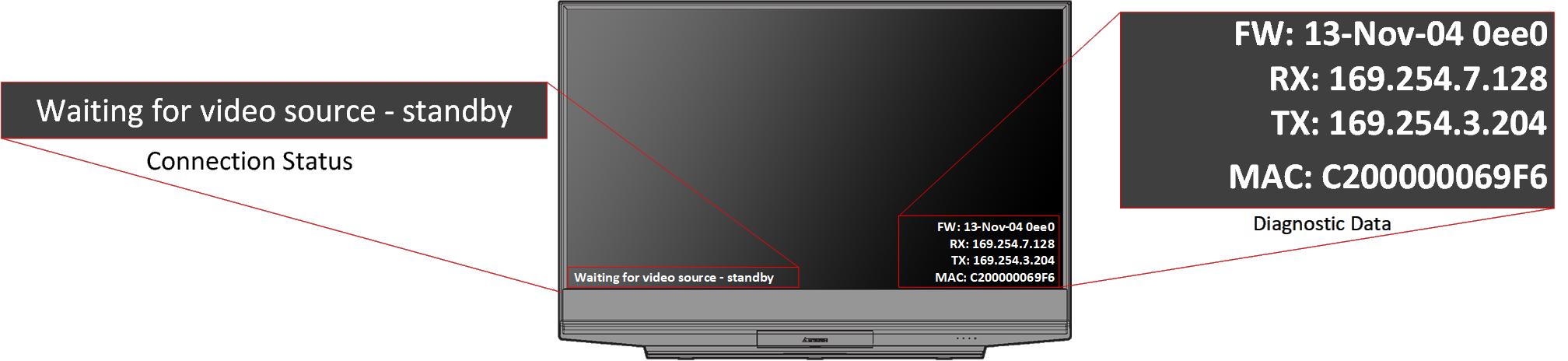
Example 2G Decoder diagnostic screen. Read the connection message and Remote IP value before using the table below.
| Message | What to check |
|---|---|
Network link is down |
The Decoder does not have an active network link. Reseat the cable at both ends, test with a known-working cable, and check the assigned switch port. A PoE Decoder can have power while its data link is down. |
Trying to find gateway... or Connecting to Transmitter... |
Check that the selected Encoder is powered and connected, then switch the Decoder to a known-working Encoder and back. If the system uses VLAN switching, verify the assigned switch ports and current source selection. Confirm compatible firmware and 2G Mode where mixed-generation devices are installed. |
All services initialized - please standby... |
This can appear during startup. If it remains on screen, check the selected Encoder, its HDMI input, and whether a different known-working source appears on this Decoder. |
Waiting for video source - please standby... or Connected - waiting for HDMI source... |
The Decoder has reached the selected Encoder but does not have usable source video. Confirm the source is on and outputting a supported signal. Reseat or replace the source-to-Encoder HDMI cable, then test another known-working source or Encoder. |
DHCP client leasefail |
The device is configured to obtain an address through DHCP but has not received a lease. Check the expected IP configuration and DHCP availability for that network. Record the existing settings before changing the device configuration. |
If the display shows no diagnostic screen, also check that the display is on the correct input, the Decoder-to-display HDMI cable is seated, and the Decoder has completed startup. A display or HDMI output problem can hide diagnostic information even when the Decoder is running.
Isolate the Fault
- Switch the affected Decoder to a known-working Encoder. If video appears, focus on the original source, HDMI cable, Encoder, and its switch connection.
- Switch another known-working Decoder to the affected Encoder. If the same problem appears there, focus on that Encoder or source path.
- If the problem stays with one Decoder, test its HDMI cable and display input, then its network cable and switch port.
- If basic checks do not identify the cause, power cycle the affected device and observe its startup and diagnostic message again. Use a known-working device swap test to determine whether the fault follows the hardware or stays with the location.
For an issue affecting devices on multiple switches, also check the inter-switch links and available bandwidth. A working link at each endpoint does not establish that the path between switches can carry the required video traffic.
Check Firmware and 2G Mode
Compare the complete firmware versions of the affected Encoder and Decoder with devices that work in the same system. Confirm that any compatible Omega Series or Ultra Series device intended to work with 2G Series hardware is operating in 2G Mode.
- Identify the firmware version of a 2G Series device
- Set 2G Mode for Omega Series and Ultra Series devices
- Update firmware on a 2G Series device
Before updating firmware: Identify the device model and current firmware version, select the matching firmware file, and check whether an incremental update is required. Do not interrupt an update in progress. The firmware table in the original troubleshooting PDF ends in 2014 and must not be used to select current firmware.
Recovery and Next Steps
Factory default is a recovery step after the device and system settings have been documented. It erases the device configuration and reboots the device; the default network mode is Auto IP with an address in 169.254.x.x/16. Follow How to Factory Default a Device (2G Series) for the current webUI, Telnet, or debug cable procedure. Do not use the older PDF's combined reset command as a general troubleshooting step.
If the issue remains, provide Just Add Power Support with the affected model numbers, firmware versions, LED patterns, exact diagnostic messages, selected source, switch ports, and results of the source switching and swap tests.
Historical reference: The original 2G Device Troubleshooting PDF is retained for reference. Use the current linked procedures above for power specifications, firmware updates, and factory defaults.

